Toyota Pickup Brake Bible

Chassis, suspension, tires, etc
Post Reply
User avatar
Provience
Actually Wheels
Posts: 329
Joined: Fri Mar 27, 2020 5:15 pm
Location: USA
Has Liked: 2 times

Toyota Pickup Brake Bible

Post by Provience »

i'd like to get all of the information i've collected over the years concerning brakes and toyota axles into one spot

handy links, by all means let me know who else should be in the top post.

http://frontrangeoffroadfab.com/ <- brackets to make things easy

https://www.autozone.com/ <- the best vehicle fitment guide to find crossover vehicles based on part number

https://www.rockauto.com/ <- easiest single source to find detailed information from MFG's without digging through MFG websites

first post saved to use for links make it easier to jump around this thread, and we'll see if we can go in chronological order :rasta: lots of this information is from rock-auto and autozone, as their websites give about the most detail, as well as things i've measured myself and things from conversations with others

i'm sure there will be errors, feel free to chime in and discuss

Toyota Solid Axle Brake Information (79-85)

Landcruiser FJ-60 Brake Information (80-90)

Toyota IFS Pickup Brake Information (86-95)

Tacoma Brake Information (95-04)

Lexus GX470 Brake Information (03-09) also select 03-09 4runner, 07-09 FJ Cruiser, 01-07 Sequoia, 00-06 Tundra

Toyota 4runner Premium/TRD/17" wheel Brake Information (17+)

Brake Pad Compound Information

Physics of Braking Systems

Concerns regarding caliper and line plasticity

anyways, give me a day or a week and i'll fill in the blanks. apparently today is easter
Last edited by Provience on Sun Apr 12, 2020 9:03 pm, edited 2 times in total.
Up is difficult, down is dangerous

User avatar
Provience
Actually Wheels
Posts: 329
Joined: Fri Mar 27, 2020 5:15 pm
Location: USA
Has Liked: 2 times

Re: Toyota Pickup Brake Bible

Post by Provience »

Toyota Solid Axle Brake Information. 79-85

Master Cylinder: 7/8" Diameter
Booster: Vacuum Single 8.56" Diameter

Rotor:
Bendix PRT1224
11.8" O/D
0.49" nominal new thickness
1.9" overall height
Weight: under 11lbs

Mounts Inboard of the hub

For lightweight and 'normal' driving, they hold up just fine. being solid, they don't dissipate heat as well as vented rotor. If this were going into a race car, you could drill them and save even more weight, but do expect them to wear out quickly and be replaced often during a season.

Calipers:
4 Piston Fixed
43MM diamter pistons
M10x1.0 inlet thread

this is the base that everything is compared against

i've got some in the garage and i'll take some pictures to add. without trying very hard, i didn't find any pictures of the stock setup on the internet.

Here is a pic from Zidaro off pirate posting a stock photo from Skys Offroad. this shows how to buy and install their spacer to go behind an IFS hub to run stock SA rotors and calipers. So if we ignore the spacer, that is what the stock setup looks like

In case i'm not clear, this (IFS hub with a spacer for solid rotor) is they dumbest thing to spend money on and do.
solid axle with spacer.jpg
solid axle with spacer.jpg (113.55 KiB) Viewed 3548 times
Here is also a picture stolen from 4rnrrick, his picture or not, screw that dude for deleting so many of his threads, but at least this pic survived. this is a profile shot of the IFS (left) hub vs the SA (right) hub, note the only difference is where the wheel mount flange is.
sa vs ifs hub.jpg
sa vs ifs hub.jpg (24 KiB) Viewed 3548 times
Last edited by Provience on Mon Apr 13, 2020 5:45 pm, edited 7 times in total.
Up is difficult, down is dangerous

User avatar
Provience
Actually Wheels
Posts: 329
Joined: Fri Mar 27, 2020 5:15 pm
Location: USA
Has Liked: 2 times

Re: Toyota Pickup Brake Bible

Post by Provience »

Toyota Landcruiser FJ 60 80-90

Master Cylinder: 7/8" Bore
Booster: Vacuum Dual 8.73" Diameter

Rotor:
Bendix PRT1510
11.8" O/D
0.785" nominal new thickness
1.9" overall height
Weight: 15.25 lbs

Mounts inboard of the hub

The FJ 60 uses the same axle outers as the mini truck, but is a heavy pig so toyota gave it vented brakes. this is a straight forward swap, so these rotors still bolt to the inboard of the hub, added benefit the internal venting and extra mass for heat capacity.

Calipers:
4 Piston Fixed
43MM/34MM diameter mismatched pistons first time in my life i ever really thought about it, the mismatched pistons are probably for 'quick takeup'. with the same input pressure, they cylinders will move at different speeds until they bottom out the pad on the rotor
M10x1.0 inlet thread

the FJ 60 brake rotors using the 1986+ V6 pickup calipers, which are all 43mm piston for vented rotors is the best cheap option for folks running heavier rigs on toyota axles who want to keep the solid axle wheel hubs to take advantage of the narrower track width and tighter scrub radius

Here is a picture of some complete FJ60 hubs with brakes from Specter Off Road https://www.sor.com/cat084.sor these guys have everything you could want for these parts, an easy to use website and, best of all, a picture that looks good :razz: i've never used them personally
FJ 60 hubs.jpg
FJ 60 hubs.jpg (63.44 KiB) Viewed 3546 times
Last edited by Provience on Mon Apr 13, 2020 5:45 pm, edited 8 times in total.
Up is difficult, down is dangerous

User avatar
Provience
Actually Wheels
Posts: 329
Joined: Fri Mar 27, 2020 5:15 pm
Location: USA
Has Liked: 2 times

Re: Toyota Pickup Brake Bible

Post by Provience »

Toyota Pickup/4runner IFS 86-95

Master Cylinder: 7/8" Bore (4cyl) 1-1/16" Bore (V6)
Booster: Vacuum Single 9.57" Diameter (4cyl) Vacuum Dual 9.73" Diameter (V6)

Rotor:
Bendix PRT1408
11.4" O/D
0.79" nominal new thickness
2.5" overall height
Weight: under 13 lbs

Mounts Inboard of the hub

1986 toyota upgraded to IFS, to make it work at least halfway decent, they also went wider. round about 1-1/2" per side to be exact :rasta: these rotors are still mounted inboard of the hub and are internally vented. they are only useful in their stock application.

Calipers:
4 Piston Fixed
43MM diameter pistons (V6) 43/34MM diameter mismatched pistons (4cyl)
M10x1.0 inlet thread

Here is a picture of a 1995 stock application front. notice the disc mounts behind the hub, also notice that this later style hub doesn't have the "ears" that the earlier ones do to cut off, it is all round, so it would all need to be ground down to use with a slip on style rotor
1995 front wb.jpg
1995 front wb.jpg (68.49 KiB) Viewed 3544 times
photo from here http://autospacover.com/how-to-replace- ... rings.html
Last edited by Provience on Sun Apr 12, 2020 4:07 pm, edited 3 times in total.
Up is difficult, down is dangerous

User avatar
Provience
Actually Wheels
Posts: 329
Joined: Fri Mar 27, 2020 5:15 pm
Location: USA
Has Liked: 2 times

Re: Toyota Pickup Brake Bible

Post by Provience »

Toyota Tacoma/4Runner 95-04

Master Cylinder: 1.0" Bore
Booster: Vacuum Dual 9.73" Diameter

Rotor:
Bendix PRT5078
11.7" O/D
0.87" nominal new thickness
2.76" overall height
Weight: 13.5 lbs

Mounts Outboard of the hub

Finally in the mid-90's toyota went to a slip on rotor. Personally, i'm a fan as it makes it easier to service the brakes and the axles and, while unlikely to cause problems, i greatly prefer to clamp the rotor between the wheel and the hub instead of using the bolts on the back of the hub and the stud heads. This rotor offers a slightly smaller O/D than the FJ60 and is slightly wider. There is no mechanical advantage of this over the FJ60 in terms of performance, any difference in heat capacity made up by extra width and venting is likely offset by the slight loss in mass.

Calipers:
4 Piston Fixed
43MM diamter pistons
M10x1.0 inlet thread

These are the most common rotors to use with modified IFS hubs if you want slip on rotors for your toyota solid axle and want to be sure you can clear 15" wheels. They work well with the same IFS calipers you used to get the hubs from.

This is a picture of a tacoma rotor (left) next to a solid axle rotor (right) mounted to an axle
tacoma vs SA rotor.jpg
tacoma vs SA rotor.jpg (47.45 KiB) Viewed 3574 times
here is a before (left) and after (right) showing how much material needs to be removed from an IFS hub in order to allow for a slip on rotor. This was done with a grinder, doesn't need to be perfect, just needs to clear. no reason to use a lathe unless you want to be fancy. I turned down a rear shaft to take a tacoma rotor, and went down to 6.650" O/D for clearance. . again, this doesn't need to be precise or round, but if you want to measure, that number works. same amount for any of the toyota slip over rotors.
IFS Hub Cut Down.jpg
IFS Hub Cut Down.jpg (47.26 KiB) Viewed 3574 times
and this is what it looks like, toyota solid axle (FJ40/60 axles same), late 80's IFS hub cut down, late 90's Tacoma rotor, late 80's IFS caliper mounted to the stock caliper mount ears, using ~1/8" spacers (washers) between the caliper and the mounting ears, caliper mounted outboard. I drilled all the way through the caliper ears and caliper mounts and used a nut/bolt to hold it together, many folks just tap the caliper ears and just use a bolt. this uses the solid axle spindle and solid axle locking hub body and increases your wheel mounting surface about 1-1/2" out per side.

The ONLY thing used from the IFS truck is the caliper and the wheel bearing hub body.
The ONLY advantage over the FJ60 rotors is easier maintenance.
Front Brakes Done.jpg
Front Brakes Done.jpg (25.28 KiB) Viewed 3574 times
Last edited by Provience on Sun Apr 12, 2020 10:22 pm, edited 4 times in total.
Up is difficult, down is dangerous

User avatar
Provience
Actually Wheels
Posts: 329
Joined: Fri Mar 27, 2020 5:15 pm
Location: USA
Has Liked: 2 times

Re: Toyota Pickup Brake Bible

Post by Provience »

Lexus GX470 03-09 also select 03-09 4runner, 07-09 FJ Cruiser, 01-07 Sequoia, 00-06 Tundra...basically everything toyota was putting out post 2004.

there are more variations on this stuff, in 2007+ the tundra went to a 5 lug :shaking: pattern, obviously we want to stick with 6 lug stuff. all the hub bores are big enough to fit :) toyota played around with more options during this time, so just looking for a 2008 4runner won't always get you the same rotor. The GX470 only came with 1 size, and it is the largest 4runner sport rotor, so that is why it is the header option. you can't go wrong if you pick up GX470 stuff.

04+ 2wd and 4cyl tacomas and 4runners and tundras get a slight upgrade from previous years.

Master Cylinder: 13/16" Bore
Booster: Vacuum Single 11.25" Diameter

Rotor:
Bendix PRT5458
12.55" O/D
1.02" nominal new thickness 1.02"
2.65" overall height
Weight: 18.5 lbs

Mounts Outboard of the hub.

These offer some significant mechanical advantage over the FJ60 rotors with about 3/4" extra diameter, this nets and effective increase of about 3/8" in the 'lever arm' that the brake pads get. They also offer an increase in thickness and mass to handle more heat, more better. The mounting ear on the caliper makes up for the rotor height change, no difference to the knuckle side mount between the 12.55" and the 13.3" rotor setups.

Calipers:
4 piston fixed WL
45MM diameter pistons
M10x1.0 inlet thread
WL caliper ear height.jpg
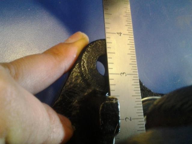
WL caliper ear height.jpg (30.6 KiB) Viewed 3572 times
GX470/4runner sport etc.

Master Cylinder: ? will need to take a note next time i'm at a junkyard. tundra's were running either 13/16 or 15/16, so i'd imagine it's right in there
Booster: ? again based on the tundra, should be about an 11" single diaphragm vacuum or looks like GX470 had hydraulic booster as an option

Rotor:
Bendix PRT5457
13.3" O/D
1.1" nominal new thickness
2.64" overall height
Weight: 20.6 lbs

again we are increasing mass and increasing our effective lever arm again. more mass = more heat, longer lever arm = more braking torque potential = more horsepower! everybody like horsepower, right? :cheers:

Calipers:
4 piston fixed WH
45MM diameter pistons
M10x1.0 inlet thread
WH caliper ear height.jpg
WH caliper ear height.jpg (33.42 KiB) Viewed 3572 times
All of these calipers have a spread that is about 1/2" greater than the toyota solid axle and older pickup/4runner stuff. Front range offroad makes the easiest way to get all these calipers mounted, it isn't terribly difficult to make your own brackets though.
WH caliper IFS hub.jpg
WH caliper IFS hub.jpg (88.4 KiB) Viewed 3572 times
https://frontrangeoffroadfab.com/tacoma ... nting-kit/

can anybody confirm or deny that the 95-04 tacomas use the same caliper ear mount spacing as the 04+?

Here is a picture of the GX470 rotor and caliper (left) and the early tacoma rotor and 80's IFS caliper (right)
tacoma vs gx470 brakes.jpg
tacoma vs gx470 brakes.jpg (67.53 KiB) Viewed 3572 times
here is a picture showing the clearance of the GX470 rotors, using the FROR mounting bracket to a 16.5" steel wheel. These calipers are thick enough that i'm going to add a 1/4" spacer to the front to clear the wheel. this depends fully on whatever style wheel you are running, this is about as much rotor as i can fit without going custom

Of note: i've got my caliper mounted in front of the axle instead of behind (as FROR suggests) biggest challenge it creates is access to the mounting bolts around the steering arms. there is no performance consideration at what degree around the clock you mount your caliper. In general, the top half helps keep it clean and out of the dirt, and keep the bleed screw above everything else.
13wh FROR installed.jpg
13wh FROR installed.jpg (81.24 KiB) Viewed 3572 times
Last edited by Provience on Sun Apr 12, 2020 3:05 pm, edited 2 times in total.
Up is difficult, down is dangerous

User avatar
Provience
Actually Wheels
Posts: 329
Joined: Fri Mar 27, 2020 5:15 pm
Location: USA
Has Liked: 2 times

Re: Toyota Pickup Brake Bible

Post by Provience »

Toyota 4runner TRD Pro 2017+ and all the other ultralux packages with 17" wheels

Rotor:
Bendix PRT6066
13.3" O/D
1.26" nominal new thickness
2.6" overall height
Weight: 22 lbs

huh, can't find any information on the caliper dimensions easily :homer: i'll look more in to that later.

these are the the biggest, heaviest and widest rotors that toyota has put out in the 6x5.5 pattern. you do get more heat capacity, but no mechanical advantage over the slightly thinner GX470 rotors.
Last edited by Provience on Sun Apr 12, 2020 2:26 pm, edited 1 time in total.
Up is difficult, down is dangerous

User avatar
Provience
Actually Wheels
Posts: 329
Joined: Fri Mar 27, 2020 5:15 pm
Location: USA
Has Liked: 2 times

Re: Toyota Pickup Brake Bible

Post by Provience »

quick note on wheel studs, I run the same stock toyota IFS front wheel stud all over on my pile. front and rear, they've worked with stock brakes, tacoma brakes, with ~1/2" spacers and now will be with GX470 brakes and 1/4" spacers. M12x1.5 and i haven't felt the need for more thread or a longer stud, these are the CHEAP way to go, feel free to spend $100+ on ARP if you want. Local auto parts store, pick a 4runner or pickup from 1986-2004 (and probably more years than that) and get what they have.
wheel studs.jpg
wheel studs.jpg (45.05 KiB) Viewed 3572 times
i'm going to go back and add some more info later

here is a picture with how much stud that leaves with a slip on rotor and pressed into a semi-float shaft
rear installed.jpg
rear installed.jpg (86.89 KiB) Viewed 3561 times
here is an example of how much is left on the front, i was using washers to measure for wheel spacer thickness needed, this looks to be with about 0.100" worth of shim.
front stud height.jpg
front stud height.jpg (74.81 KiB) Viewed 3561 times
Up is difficult, down is dangerous

User avatar
Provience
Actually Wheels
Posts: 329
Joined: Fri Mar 27, 2020 5:15 pm
Location: USA
Has Liked: 2 times

Re: Toyota Pickup Brake Bible

Post by Provience »

Alright, well those cover the basic hard components. Just for reference, i bought new rotors/pads/calipers/core charge/fror brackets/spacers to run the GX470 stuff and it cost me <$450. When i did the tacoma rotors during my solid axle swap, all i had to buy were rotors <$50

https://www.pirate4x4.com/forum/newbie- ... isons.html <- i'm going to :spam: this thread because it's my thread over there. please read over there for more info and discussion, i'm going to copy over a bunch of it, mostly it was myself, ISDTBlower and Arse Sideways.

The brake pad is the next thing that we get in to. there aren't always a ton of options, but sometimes there are options. The codes will be printed on the side of the pad. below is an example of an FE pad. first letter is the Friction Coefficient at low temp, 0-200*. Second letter is at high temp, 200-600*. high friction coefficient means more braking force and more wear. Brakes are wear parts, do not build a high performance system for your race car and bitch that they don't last long :flipoff:
IMG_2894.JPG
https://www.hotrod.com/articles/hrdp-10 ... echnology/
Friction Coefficient Code
Up to 0.15 µ C
Over 0.15 µ up to 0.25 µ D
Over 0.25 µ up to 0.35 µ E
Over 0.35 µ up to 0.45 µ F
Over 0.45 µ up to 0.55 µ G
Over 0.55 µ H
Unclassified Z
https://www.michigan.gov/documents/msp/ ... 7522_7.pdf

this is a link to a neat PDF that the Michigan Police did concerning brake pads on their cruisers

https://www.tbmbrakes.com/brake-pad-compounds/

TMB brakes has good information concerning the pad compounds and CoF and has this chart to go with it as a 'rule of thumb' for picking drag race pads
TBM #1 (STANDARD DRAG RACE KIT PAD, REFER TO CHART BELOW)
Maximum temperature 500°F, .60 CoF.
Designed for rapid yet smooth application.
Typical Use: Drag Racing

TBM #85 (STANDARD DRAG RACE KIT PAD, REFER TO CHART BELOW)
Maximum temperature 1500°F, .58 CoF.
Extremely high initial bite with high, stable friction across temperature range. Improved pad and rotor wear rate over #84, the most rotor friendly “high-torque” brake pad.
Typical Use: Asphalt Oval, Road Racing, Drag Racing

TBM #82 (STANDARD STREET REPLACEMENT FOR DRAG KIT #85 OR #1 PAD)
Maximum temperature 500°F, .44 CoF.
Very-low dust, noiseless, ceramic brake pads for street cars under normal driving conditions.
Typical Use: Performance Street

TBM #84
Maximum temperature 1400°F, .56 CoF.
High initial bite with rising friction as temperature increases. Excellent high temperature wear rate. Moderate rotor wear.
Typical Use: Asphalt Oval, Road Racing, Monster Truck, Dirt Track
drag-racing-brake-pad-selection-chart.png
I brought the #82 pad over as an example of just how much CoF and temp tolerance is lost by going to a 'street' pad, and that is a pretty good street pad. they also make high temp pads with lower CoF that are more dirt tolerant and not as aggressive.

I thought there was some discussion in that thread regarding ceramic vs semi-metallic, guess not. the short of the long of it is, it doesn't matter nearly as much WHAT the pads are made out of compared to what performance spec they are made to. Yes, ceramic don't make as much visible dust on your wheels :rasta:, but no, they don't work better simply because they are ceramic.

Here is some info from Hawk Performance and their DTC 50 compound, this is their pre-runner/TT truck pad
https://www.hawkperformance.com/motorsports
DTC-50
Hawk's DTC-50 is what racers have been asking for: a pad that can be used as a split compound for tuning, and an endurance compound that can be used at the highest levels of racing. DTC-50 was developed through extensive testing, giving racers a pad that enhances our line of Dynamic Torque Control products and bridges the temperature and brake torque range between our current DTC-30 to DTC-60 race pads. This new compound offers consistent performance across a wide range of temperatures, while providing very high torque and aggressive initial bite.

Very high torque

Aggressive initial bite
Excellent modulation and release characteristics
High temperature fade resistance
Designed for high deceleration rates
All Hawk Performance compounds are not compatible with carbon ceramic rotors. Hawk pads are designed to work with Iron/Metal rotors.
High torque
500-1100 F operating temperatures
500-1100 F optimal temperature range
dtc 50.jpg
dtc 50.jpg (26.84 KiB) Viewed 3531 times

well, let's put it in to perspective with compound and lever arm, using a static pressure amount. quoting myself, i'll get the maths i used up in another post. the numbers themselves are less important than the change relative to each other
using a theoretical line pressure of ~1255 psi and adjusting one at a time the CoF for different brake pad ratings vs going up in rotor diameter

4.3 Reff is the effective radius of about a 10.5" brake rotor.
5.3 Reff is about a 12.5" rotor
6.3 is about a 14.5" rotor

0.3 is mid range of EE friction rating
0.4 is mid range of FF friction rating
0.5 is mid range of GG friction rating
brake chart table crop.png
brake chart table crop.png (9.37 KiB) Viewed 3528 times
the numbers listed in the middle are the foot pounds of torque effected on the given rotor with the given friction rated pad at the constant 1255 caliper PSI input

What does this show? well for the same friction rating, going up 1" in effective radius from 4.3 to 5.3 realizes a 25% increase in braking torque

going from 5.3 to 6.3 realizes a 18% increase in braking torque

going from 4.3 to 6.3 realizes a 47% increase in braking torque

using the same rotor and changing the pad;

from EE to FF realizes 33% gain

FF to GG realizes 25% gain

from EE to GG realizes a 66% gain

working at the angle, going from a 4.3 and EE to 5.3 and FF is a 66% gain

5.3 FF to 6.3 GG is 47% gain

well if you are limited on space be aware of the friction rating on your pad and see if you can find one that gives you some increase. Granted, you can fall into a range with the pad and have some be at the top or bottom of the range, but on average you get a jump in 'theoretical' available braking torque of greater amount by increasing one letter rating than you do for increasing 1 inch of effective radius arm (or 2" in rotor diameter)
Last edited by Provience on Sun Apr 12, 2020 7:10 pm, edited 5 times in total.
Up is difficult, down is dangerous

User avatar
Scott Cee AKA 2drx4
Trail Tamer
Posts: 2017
Joined: Mon Sep 16, 2019 10:59 pm
Location: Prince George, BC
Has Liked: 139 times
Been Liked: 47 times
Contact:

Re: Toyota Pickup Brake Bible

Post by Scott Cee AKA 2drx4 »

Provience wrote: Sun Apr 12, 2020 4:26 pm The brake pad is the next thing that we get in to. there aren't always a ton of options, but sometimes there are options. The codes will be printed on the side of the pad. below is an example of an FE pad. first letter is the Friction Coefficient at low temp, 0-200*. Second letter is at high temp, 200-600*. high friction coefficient means more braking force and more wear. Brakes are wear parts, do not build a high performance system for your race car and bitch that they don't last long :flipoff:
Well, colour me surprised, I learned something that might actually be relevant in a Toyota brake thread. :ideas:

User avatar
Provience
Actually Wheels
Posts: 329
Joined: Fri Mar 27, 2020 5:15 pm
Location: USA
Has Liked: 2 times

Re: Toyota Pickup Brake Bible

Post by Provience »

Scott Cee AKA 2drx4 wrote: Sun Apr 12, 2020 5:01 pm
Provience wrote: Sun Apr 12, 2020 4:26 pm The brake pad is the next thing that we get in to. there aren't always a ton of options, but sometimes there are options. The codes will be printed on the side of the pad. below is an example of an FE pad. first letter is the Friction Coefficient at low temp, 0-200*. Second letter is at high temp, 200-600*. high friction coefficient means more braking force and more wear. Brakes are wear parts, do not build a high performance system for your race car and bitch that they don't last long :flipoff:
Well, colour me surprised, I learned something that might actually be relevant in a Toyota brake thread. :ideas:
:lmao: well maybe tonight or tomorrow, everything else that gets added will be generally applicable stuff. i'm going to try to figure out how to condense down some of the longer posts over there and get up the testing for various line types and kind of work backwards from the tire and get into some master cylinder sizing and booster calculations and pedal configurations.
Up is difficult, down is dangerous

User avatar
Provience
Actually Wheels
Posts: 329
Joined: Fri Mar 27, 2020 5:15 pm
Location: USA
Has Liked: 2 times

Re: Toyota Pickup Brake Bible

Post by Provience »

https://www.academia.edu/4407937/The_Ph ... ng_Systems

https://www.apcautotech.com/brands/cent ... s/stoptech

so stoptech has apparently been acquired or some such and their tech articles seem lost to space. Fortunately, the internet is space and this random academia.edu has saved a copy of the article :rasta:

to help future proof this here bible, i'm going to directly copy/paste formula from there and take screenshots to upload pictures directly, as appropriate

"The Physics of Braking Systems" by James Walker, Jr. of scR motorsports copyrighted by stop tech LLC, but fuck them for getting bought out and then the new owners changing shit and removing this information off the internet, or making it so that i can't find it. It's only been 15 years. Change is bad.
Author’s disclaimer: mechanical systems operating in the physical world are neither 100% efficient nor are they capable of instantaneous changes in state. Consequently, theequations and relationships presented herein are approximations of these braking systemcomponents as best as we understand their mechanizations and physical attributes.Where appropriate, several examples of limiting conditions and primary inefficiencieshave been identified, but please do not assume these partial lists to be all-encompassingor definitive in their qualifications
Conservation of Energy
The braking system exists to convert the energy of a vehicle in motion into thermalenergy, more commonly referred to as heat. From basic physics, the kinetic energy of a body in motion is defined as:

Kinetic Energy = 1/2*m*v^2

m=mass of vehicle; v=velocity

Ideally, this energy is completely absorbed by the braking system. While this is notentirely the case, for a stopping event at maximum deceleration most of the vehicle’skinetic energy is converted into thermal energy as defined by

1/2*m*v^2 => M*C*deltaT

the M=mass of braking system; C=specific heat of braking system which absorbs energy; deltaT=temperature rise experienced

note that for most single-stop events, the rotors serve as the primary energy absorbing components
Brake Pedal
The brake pedal exists to multiply the force exerted by the driver’s foot. Fromelementary statics, the force increase will be equal to the driver’s applied force multiplied by the lever ratio of the brake pedal assembly

F = f*{L2/L1}

F = force output of pedal assembly; f = driver applied force; L2 = distance from pivot to brake pedal pad (input) ; L1 = distance from pivot to clevis rod (output)
i'm adding a quote of myself into here, because that paper ignores the booster
Pi*R*2 = surface area of brake booster diaphram.

Diaphram area*generated PSI= output force

generated PSI from the engine, hook up a vacuum gauge and read the manifold vacuum at idle, or measure it under decel if you want to get fancy and often go WOT to close. Let's say you generated 22 inhg, subtract ambient air pressure of 14 (acts on both sides of the diaphram) and you get 8 psi of effort generated from the engine.

If you have an engine that makes very low idle vacuum, anything near 14 and especially under 18, consider a small 12v vac pump or add on an engine driven vac pump depending on what fits where the best

below example uses 7" single booster with an engine that generates 22 inhg manifold vacuum

Pi(3.14) X radius(3.5)2 = 38.46 sq/inches of diaphragm surface area X 8 psi (negative pressure becomes positive force)= 307.72 lbs of output force
Master Cylinder
It is the functional responsibility of the master cylinder to translate the force from the brake pedal assembly into hydraulic fluid pressure. Assuming incompressible liquids and infinitely rigid hydraulic vessels, the pressure generated by the master cylinder will beequal to:

P = F/A

P = hydraulic pressure generated; F = force output of pedal assembly; A = effective bore area
Fluid, Brake Pipes, and Hoses
It is the functional responsibility of the brake fluid, brake pipes, and hoses to transmit thehydraulic fluid pressure from the master cylinder to the calipers located at the wheel
ends. Out of necessity, part of this subsystem must be constructed from flexible(compliant) materials, as the wheel ends are free to articulate relative to the vehicle’sunsprung mass (most commonly known as the body structure). However, again assumingincompressible liquids and infinitely rigid hydraulic vessels, the pressure transmitted tothe calipers will be equal to

P=P

P = hydraulic pressure generated at the master cylinder is equal to hydraulic pressure seen at the caliper
Caliper, Part I
It is the first functional responsibility of the caliper to translate the hydraulic fluid pressure from the pipes and hoses into a linear mechanical force. Once again assumingincompressible liquids and infinitely rigid hydraulic vessels, the one-sided linear mechanical force generated by the caliper will be equal to:

Fc=P*A

Fc = one sided linear force of the Caliper; P = caliper input pressure; A = effective area of pistons found on one half of the caliper
Caliper, Part II
It is the second functional responsibility of the caliper to react the one-sided linear mechanical force in such a way that a clamping force is generated between the two halvesof the caliper body. Regardless of caliper design (fixed body or floating body), theclamping force will be equal to, in theory, twice the linear mechanical force as follows

Fcl=Fc*2

Fcl = Clamping force of the caliper; Fc = one sided caliper force; 2 = two, for both halves :flipoff:
Brake Pads
It is the functional responsibility of the brake pads to generate a frictional force whichopposes the rotation of the spinning rotor assembly. This frictional force is related to thecaliper clamp force as follows:

Fr = Fcl*CoF

Fr = frictional force generate; Fcl = caliper clamping force; CoF = Coefficient of Friction between Pads and Rotors
Rotor
While the rotor serves as the primary heat sink in the braking system, it is the functionalresponsibility of the rotor to generate a retarding torque as a function of the brake pad frictional force. This torque is related to the brake pad frictional force as follows:

Tq = Fr*Reff

Tq = torque generated by rotor; Fr = Frictional force generated; Reff = effective radius of the rotor (measured from rotor center to center of pressure from caliper pistons)
Tire
Assuming that there is adequate traction (friction) between the tire and the road toaccommodate the driver’s braking request, the tire will develop slip in order to react the torque found in the rotating assembly. The amount of slip generated will be a function of the tire’s output characteristics (the mu-slip relationship), but the force reacted at theground will be equal to:

Ft = Tq/Rt

Ft = Force Tire, force between tire and the ground; Tq = rotor torque generated; Rt = effective rolling radius of loaded tire
To find total vehicle, don't forget to SUM Ft for all 4 tires
Deceleration of a Vehicle in Motion
Based on the work of Sir Isaac Newton, if a force is exerted on a body it will experience acommensurate acceleration. Convention dictates that accelerations which oppose thedirection of travel are called decelerations. In the case of a vehicle experiencing a braking force, the deceleration of the vehicle will be equal to

Av = Ftot/m

Av = vehicle deceleration; Ftot =sum of total tire braking force; m = vehicle mass
Kinematics Relationships of Vehicles Experiencing Deceleration
Integrating the deceleration of a body in motion with respect to time allows for thedetermination of speed. Integrating yet again allows for the determination of position.Applying this relationship to a vehicle experiencing a linear deceleration, the theoreticalstopping distance of a vehicle in motion can be calculated as follows

SD = v^2/(2*Av)

SD = Stopping Distance; V = velocity; Av = Vehicle deceleration
And now that i've summarized a whole bunch, i'm going to print screen, paste as image the last couple pages
weight dist.png
weight dist.png (114.39 KiB) Viewed 3524 times
weight dist 2.png
weight dist 2.png (80.88 KiB) Viewed 3524 times
weight dist 3.png
weight dist 3.png (105.03 KiB) Viewed 3524 times
weight dist 4.png
weight dist 4.png (111.43 KiB) Viewed 3524 times
weight dist 5.png
weight dist 5.png (43.53 KiB) Viewed 3524 times
Last edited by Provience on Sun Apr 12, 2020 8:39 pm, edited 1 time in total.
Up is difficult, down is dangerous

User avatar
Provience
Actually Wheels
Posts: 329
Joined: Fri Mar 27, 2020 5:15 pm
Location: USA
Has Liked: 2 times

Re: Toyota Pickup Brake Bible

Post by Provience »

now that the math with all the disclaimers about how reality isn't 100% is out of the way, let's get in to some of that 'not 100%' stuff!

Everything is actually plastic :pimp: even calipers, higher end calipers use more heat tolerant materials. 'stock' calipers rely on the pads working as insulators to keep the heat into the rotor, and then into the air. Heat and pressure will both cause things to flex.
posted by ISDTblower: Some calipers will only take around 1600psi before they start to deform. A "racing" caliper can usually take up to around 2600psi. A key strength area is the center bridge and more wrap on the rotor.

Know that aluminum will loose half of it's strength above about 350*. One that goes to 425-450* is classed as "High Temp." Alum is generally not recommended above 300*F as it may "creep."

A vented rotor may cool a caliper somewhat...until you stop. Pads are also insulators.

From Wiki.....

Characteristics of common braking fluids[4][5]
Dry boiling point Wet boiling point Viscosity limit Primary constituent
DOT 2 190 °C (374 °F) 140 °C (284 °F) ? castor oil/alcohol
DOT 3 205 °C (401 °F) 140 °C (284 °F) 1500 mm2/s glycol ether
DOT 4 230 °C (446 °F) 155 °C (311 °F) 1800 mm2/s glycol ether/borate ester
LHM+ 249 °C (480 °F) 249 °C (480 °F) 1200 mm2/s [6] mineral oil
DOT 5 260 °C (500 °F) 180 °C (356 °F) 900 mm2/s silicone
DOT 5.1 260 °C (500 °F) 180 °C (356 °F) 900 mm2/s glycol ether/borate ester
Wet boiling point defined as 3.7% water by volume.

Brakes are not a simple catalog deal. Be-Friend a Brakeman that goes and drives at the races for the win.

Good stuff.

from the internet

copper.org did a study on longevity and such for nickle copper lines, they ran them up to pressure of 16000psi, 6000 psi and 3000 psi, cycled them a bunch and found not a bunch of loss. after 200 cycles, the burst went from 16,000 psi to above 14,000 psi on average.

pretty interesting read. from a reference in there, in 1991 it was stated that "brake system should have a burst PSI from 6,800-23,000" when analyzing failures due to corrosion and wear.

https://www.copper.org/applications/aut ... _tube.html

Stainless Steel tubing

3/16" with 0.028" wall thickness and a 4:1 safety factor yields 6,392 working PSI
3/16" with 0.035" wall yields 8,197 working PSI

increase the temperature to 500* F and it is something like a factor of .65, so the smaller line drops to 4154 safe working PSI

https://www.hydra-flex.com/v/vspfiles/a ... atings.pdf

rubber hydraulic hoses are rated in working pressure and vary greatly on design. it should be printed on the hose itself what it is rated for, material and thickness are all over the place.

as an example, MSC Direct (industrial supply) lists 3 rubber hoses with 3/16" inside diameter, 2 with working pressure of 3000 psi and 1 with 2000 psi

of the 3000 psi lines, one is rated for -40 to 302*F and the other -40 to 212*F temperature (12,000 burst psi rating on this one)

this is one of the reasons why some OEM, Toyota for example, ran a hardline from the caliper for several inches before going to a rubber line then back to a hard line. it isolates the rubber line from the heat generated that can be carried to the caliper
from Arse Sideways - Google points me to SAE J1401

Edit: J1401 is just the test procedure.

This document references an "Expansion Test" in ASTM D571-55 which I couldn't find.

I could find that "D571-76 Methods of Testing Rubber Hose for Automotive Hydraulic Brake System" was withdrawn in 1981. Technical Standards Document No. 106, Revision 1R from Canada includes a table for the maximum allowable volumetric expansion (in cubic centimeters per foot) for brake hose at three different pressures.

Also, per the same document you can probably hang calipers from brake hoses without issue.
Quote: 'S5.3.4
Tensile strength. A hydraulic brake hose assembly shall withstand a pull of 1446N (325 pounds) without separation of the hose from its end fittings during a slow pull test, and shall withstand a pull of 1646N (370 pounds) without separation of the hose from its end fittings during a fast pull test. (S6.4)'

edit2: 1cc = 0.0610237ci

Just so you have a frame of reference 1cc works out to just shy of ~0.466" of pedal travel of travel on a 60s Bronco using a 1" bore master cylinder and 6:1 pedal ratio 6:1 pedal ratio.

The conclusion I draw is that hose flex isn't a ton but it sure isn't nothing either, especially for OEM style hoses at hydro-boost pressures. For an entire vehicle, especially one with DOT brake hoses used to extend other DOT brake hoses you could definitely wind up with a couple inches of not so hard pedal just on account of the hoses flexing.
test pressure.jpg
test pressure.jpg (83.67 KiB) Viewed 3524 times
Here is a good read regarding teflon/braided lines

Brake Lines Upgrade - Modified Magazine

Quote:
When testing volumetric expansion, Goodridge found that standard OE-type rubber brake hose expanded by 0.136 cc/ft at 1,000 psi, 0.150 cc/ft at 1,500 psi, and 0.290 cc/ft at 2,900 psi, whereas the company's PTFE braided stainless hoses expanded by only 0.0002932 cc/ft at 4,000 psi.
honestly i didn't realize the 'standard' for teflon hoses was only 4250 burst PSI. just another thing to keep in mind when buying line, it is worth it to find something rated at least as good as OE rubber lines.

Quote:
When conducting the burst/working pressure test as defined by the FMVSS106 and SAE J1401 standards, Goodridge's PTFE braided hoses burst at 12,750-13,500 psi, which is triple that of the 4,250 psi required by the standard for this type of hose. By comparison, the OE rubber lines tested burst at 8,000-9,000 psi, with a recommended safe working pressure of 3,600 psi.
arse sideways brings up some points from the mark williams braketech
https://www.markwilliams.com/braketech.html
So, to continue on with the hypothetical EB (0.466" of pedal travel per CC)..

Minimum spec (1.02cc/ft) regular expansion hose (1.02cc@1500psi would get you ~0.475" of pedal travel per foot.

Minimum spec low expansion hose (0.72cc@1500psi) would get ~0.336" of pedal travel per foot.

The hose Goodyear tested (0.150cc@1500psi) would result in ~.07" of pedal travel per foot.

The PTFE with braided stainless (0.0002932cc@1500psi) would result in a hair over ~0.0001" of pedal travel per foot.

To me this raises the question of why there's so much variance in the OEM style hoses and is there the same variance in the braided stainless?

Were those Goodyear OEM hoses their top of the line product? Do the cheapest OEM lines exceed the spec by a similar amount?

How does the cheap PTFE + braided stainless compare to the Goodyear stuff?

Obviously the braided stainless stuff is the way to go regardless of length.

Another plus of having negligible flex per foot is that you can use longer hoses than the minimum in order to get larger bends and longer hose life.
Last edited by Provience on Sun Apr 12, 2020 9:05 pm, edited 1 time in total.
Up is difficult, down is dangerous

User avatar
Provience
Actually Wheels
Posts: 329
Joined: Fri Mar 27, 2020 5:15 pm
Location: USA
Has Liked: 2 times

Re: Toyota Pickup Brake Bible

Post by Provience »

Alright, not sure how i want to word this or where i want to put it.

For folks designing their system from scratch, a very reasonable Target PSI for a regular rig would be 1,500 psi hydraulic input force TO THE CALIPER and for folks looking to race, shoot for as much as you can get your caliper to handle. 2,500 psi? Talk to your supplier.

If you are running manual/unassisted brakes, play around with the math to get your line pressure up to and your input (foot) pressure down, with a travel that fits in your chassis.

hydraulic pressure has the largest impact on braking force. 'normal' input pressure for a typical foot is probably starting under 50lbs, max generated 'emergency' or hard braking is probably much closer to 1-2x body weight. As long as your system doesn't break brake parts under max effort, you are doing good. Keep in mind how much force you use for very hard braking, and thing about how much you want to use for 'normal' stops so that you don't end up with too unrealistic of expectations.
Up is difficult, down is dangerous

Post Reply