Stripped/Buggy/EFI Swap 22r/22re and Toyota Wiring Diagrams

Wiring, Electrical Troubleshooting, Radios, etc
Post Reply
User avatar
Provience
Actually Wheels
Posts: 329
Joined: Fri Mar 27, 2020 5:15 pm
Location: USA
Has Liked: 2 times

Stripped/Buggy/EFI Swap 22r/22re and Toyota Wiring Diagrams

Post by Provience »

This is some notes from a while back that I often end up referencing and directing other people to. Wanted to have a version of it hosted somewhere that I won't feel slimy using :rasta:

Also, if anybody knows how/where/what needs to be done so that I can host .pdf files instead of just image files, that would be handy as well so that folks can download and print bigger/better versions for themselves.

These diagrams have been used and shown functional by folks other than just me, for whatever that is worth.

For a tachometer reference signal, pick it up from the Negative side of the coil/ignitor

Biggest difference for the 20R is that it uses and external regulator for the alternator
20R wiring JPEG.jpg
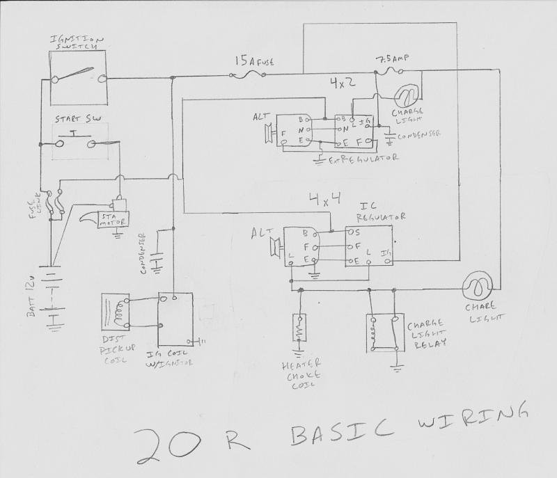
20R wiring JPEG.jpg (41.82 KiB) Viewed 8789 times
If you are running a 22R or 22RE on propane, the only difference between the below would be running the branch labeled "Choke Heater" would go to your mixing bowl. Of note, i've converted a stock toyota 3 wire alt into a 1 wire alt, that is really all it takes. If you wanted to use any other 1 wire alt, it would wire up the same. Stock 22r alt output is ~60 amps fwiw.
22R wiring JPEG.jpg
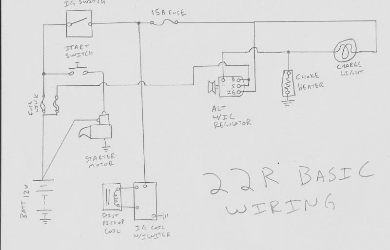
22R wiring JPEG.jpg (28.75 KiB) Viewed 8789 times
This is how i stripped down my 1989-1995 22re wiring harness when I did my EFI swap. the 2RZ, 3RZ, 3VZ and 5VZ are all very similar. the main takeaway is, find the circuits that you absolutely need. trace those wires back, keep them and remove everything else. Yes, i know there are no wire colors. the colors don't matter and they can be different depending on the year. With wiring, don't just open the harness and start hacking, follow the end component back to the source. it is VERY EASY to reloom and entire harness.

JustDSM says - You'll throw a CEL for the VSS signal being absent and about the only side effect you'll notice is that you'll have some idle speed inconsistencies since the ECU uses the VSS for idle speed strategies. It will not keep the truck from running, or running well for that matter.

Concerning ECM pinouts: open up the ECU box, physically, and the pinouts are labeled on the circuits
22RE wiring JPEG.jpg
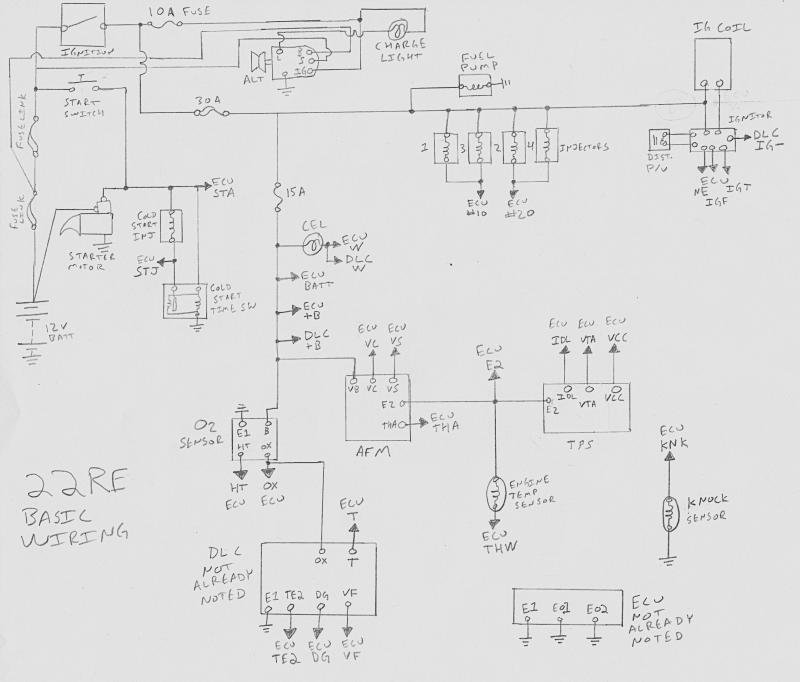
22RE wiring JPEG.jpg (49.94 KiB) Viewed 8789 times
these are from FAWK AWPH when he did his buggy. he did not use the IAC or Cold Start Injector just to clean it up a little bit more
22re buggy wire.jpg
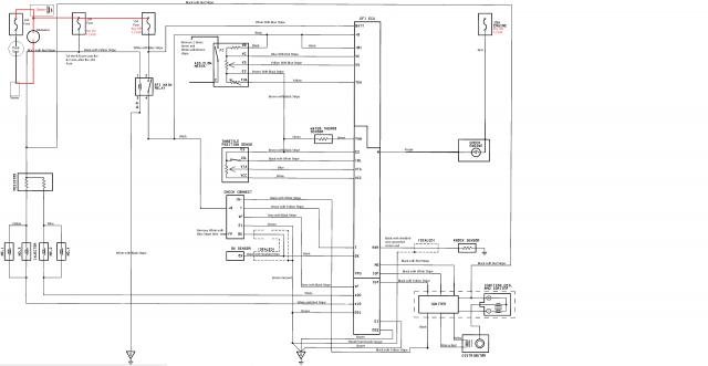
22re buggy wire.jpg (23.67 KiB) Viewed 8789 times
22re pinout.jpg
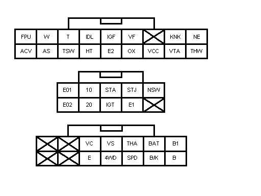
22re pinout.jpg (21.61 KiB) Viewed 8789 times
Last edited by Provience on Wed May 27, 2020 3:32 pm, edited 1 time in total.
Up is difficult, down is dangerous

User avatar
Provience
Actually Wheels
Posts: 329
Joined: Fri Mar 27, 2020 5:15 pm
Location: USA
Has Liked: 2 times

Re: Stripped/Buggy/EFI Swap 22r/22re and Toyota Wiring Diagrams

Post by Provience »

This should only be considered a general guideline for wire colors:

Let's try out the 20R


Ignition Coil

BRown to 12V+

Black to GND

Blue to Condenser


For Alt Regulator Combo labeled 4X2

B to B to Battery is White

N to N (neutral) is bLue

E to E to GND is Black

F to F (field) is Green

L to Charge Light is Yellow


for Alt Regulator Combo labeled 4X4

B to S is White

F to F is Green

E to E is Black

L to L to Charge Light is Yellow

IG to Ignition 12V+ is Red
Up is difficult, down is dangerous

User avatar
Provience
Actually Wheels
Posts: 329
Joined: Fri Mar 27, 2020 5:15 pm
Location: USA
Has Liked: 2 times

Re: Stripped/Buggy/EFI Swap 22r/22re and Toyota Wiring Diagrams

Post by Provience »

For the 22R

Alternator
L to Charge Light is Yellow
B to Battery is White
S to 12V+ is White
IG to IGnition is Red

Distributor
#1 to Igniter is Red
#2 to Igniter is White

Ignition Coil
Coil+ to Igniter is BRown
Coil- to Igniter is Black

Igniter
#1 Black-Red to Ignition 12V+
#2 Black OPTIONAL AND NOT LISTED IN ABOVE SCHEMATIC to Tachometer
GND goes to the GND and is right there
Up is difficult, down is dangerous

User avatar
Provience
Actually Wheels
Posts: 329
Joined: Fri Mar 27, 2020 5:15 pm
Location: USA
Has Liked: 2 times

Re: Stripped/Buggy/EFI Swap 22r/22re and Toyota Wiring Diagrams

Post by Provience »

22RE (these are off a '95 so may not be 100% for all years or it may apply to many generations :rasta:)


ALL PLUGS ARE NUMBERED LEFT TO RIGHT, TOP TO BOTTOM


Ignitor

Wire #1 - Black-bLue to IGT ECU

#2 - Black-Orange to NE ECU

#3 - Black-Red to 12V+

#4 - Black-Yellow to IGF ECU


Distributor

#1 to Igniter is Red

#2 to Igniter is White


Ignition Coil

Coil+ to Igniter is BRown

Coil- to Igniter is Black


Fuel Pump

#1 - bLue to 12V+

#2 - White-Black to EARTH(GND)


Injectors

#1 - Black-Red to 12V+

Injectors 1&3 #2 White-Red to #10 ECU

Injectors 2&4 #2 White to #20 ECU


AFM

#3 BRown-Black to E2 ECU

#4 White-Red to 12V+

#5 Green-Blue to VC ECU

#6 Yellow-bLue to VS ECU

#7 Yellow-Green to THA ECU


TPS

#1 BRown-Black to E2 ECU

#2 Yellow-bLue to IDL ECU

#3 Yellow to VTA ECU

#4 Green-Yellow to VCC ECU


Coolant Sensor

#1 BRown-Black to E2 ECU

#2 Green-bLue to THW ECU


Knock Sensor

#1 Black to KNK ECU


Oxygen Sensor (with heater)

#1 Pink-Green to HT1 ECU

#2 White-Red to 12V+

#3 Black to OX1 ECU

#4 BRown to E1 ECU/GND


Check Engine Light

#1 Black-Orange to 12V+

#2 Violet (purple) to W ECU and W DLC


Data Link Connector

#4 Black to OX

#3 BRown to E1 GND

#6 Violet-White to T ECU

#7 Violet-Green to E2 ECU

#9 Yellow to VF ECU

#17 Violet to DG ECU (4WD A/T only)


Alternator

GND is that one small stud nut

#1 Yellow to Light

#2 Red to IGnition

#3 White to Sense (12V+)

B is for direct to Battery and is White
Up is difficult, down is dangerous

User avatar
Provience
Actually Wheels
Posts: 329
Joined: Fri Mar 27, 2020 5:15 pm
Location: USA
Has Liked: 2 times

Re: Stripped/Buggy/EFI Swap 22r/22re and Toyota Wiring Diagrams

Post by Provience »

A conversation with artj123 that may address a similar issue for somebody else:

artj123 - this was very help full but i found that the cold start circuit was not correct for my app. i stripped an 85 efi harness and wired to the "pencil lead gray" diagram but rather than tag off the circuit between the temp sensor and the cold start injector i needed to make a loop from the sta port including the temp back to the stj port. this worked for my app.

me - Just to be clear....I've got in the diagram that the cold start injector circuit gets 12volt power from the switch for the starter solenoid going TO the Cold Start Injector and the Cold Start Time Switch (temp sensor) and then that 12v power goes to STA on the ECU.
The Cold Start Injector as well as the Cold Start Time Switch (temp sensor) receive their GND from the ECU at STJ.
Also, the Cold Start Time Switch (temp sensor) is self grounding depending on the coolant temperature.
You are saying that this did not work for you and that you had to run a wire directly connecting the STJ and STA ports? Huh...

artj123 - i got power from the start switch tied into the sta side of the computer, from there sta/power runs through both the injector and temp switch back to the the stj port. i think things are happy from what i can tell. it has been cold and seems to work but i might be wrong as well. ruff chiltons diagram showed the same thing from what i can tell. let me know if you think this is incorrect but is working for me right now? although i have had some problems with parts failing just sitting. started with running truck and parts but the injector resistor just quit? don't recall dropping it or anything but it quit. there is not much info on that out there so took awhile for me to find out that the resistor should read 12v on the injector side of things. and for what is worth thanks for all of the work on this.

me - Yes, 12v pos from switch goes to the pos side of the injector, the temp switch, and STA on the ECU.
Ground comes from STJ on ECU and goes to ground side of injector and temp switch.
That is how I've got it in my diagram as well, i just don't have the injector resistor shown. It was 88 or 89 that Toyota went away from the external resistor for the injectors, i drew my schematic off the newer style.
Up is difficult, down is dangerous

User avatar
Provience
Actually Wheels
Posts: 329
Joined: Fri Mar 27, 2020 5:15 pm
Location: USA
Has Liked: 2 times

Re: Stripped/Buggy/EFI Swap 22r/22re and Toyota Wiring Diagrams

Post by Provience »

If you have ever heard "You only need 4 wires to run a 22re", this is what that means.

YZRider - In the two plugs which connect the ECU and engine harness (C1 and C2?) to the body there are only four circuits required to run the engine. Two (black-red and white-red) from switched power which run to the injectors, coil, AFM, TPS, B, +B, etc... One (black-white) momentary power which runs to the start circuit, and one (black-green) constant hot, "BATT." Essentially, you can leave the entire engine side of the harness intact, pick up those 4 which run from the body to the engine harness, and run the engine. Anything else that runs through those two plugs is for various non-essential signals (tach, 4wd, stop, water temp, oil pressure, etc). No, it wont work on *just* 4 wires. You only need a minimum of 4 wires going to the engine harness.

obviously, a 22re takes more than 4 wires to run in total, but for a quick and easy route to EFI swap or plop one in to a buggy, the stock wiring harness that doesn't go to anything on the engine only needs 4 of the wires

image courtesy of Rokcrler of the 4 wires left in the connector:
22re 4wire.jpg
Up is difficult, down is dangerous

User avatar
Provience
Actually Wheels
Posts: 329
Joined: Fri Mar 27, 2020 5:15 pm
Location: USA
Has Liked: 2 times

Re: Stripped/Buggy/EFI Swap 22r/22re and Toyota Wiring Diagrams

Post by Provience »

freeclimber00 wrote:
I am not sure if you want this info in your thread, but thought I would add it to a thread people will read often, as long as you don't mind.

Edit: This is info from a 22R to 22RE swap I did last year.


This is wiring chart to plug a "93" wire harness into an "81" SR5 dash cluster.


I got this dash harness figured out for those that are afraid to do this without a little help.....I know how scary it is without help, but I am the type to dive into murky waters for the better of mankind. I will get a few pics up tomarrow.


First off, you have to look at the plugs and do some counting. There are 4 plugs on the 93 harness a White 8 pin, White 10 pin, Blue 12 pin, White 12 pin. There only a couple that you will need to count from, but it's important.


All the numbers that are listed below are from the 81 plugs, they are numbered, find the #'s.


Small Plug Dial on the 81 Harness.

-------------------------------------------------------------------------

# / 1981 / 1993 / Use

-------------------------------------------------------------------------

1./ YEL-BLK / YEL-BLU / OIL IND.

2./ YEL-GRN / YEL-GRN / TEMP. GAUGE

3./ RED-GRN / RED-GRN / HI-BEAM

4./ RED-BLK / / Term. , not used

5./ YEL-RED / YEL-RED / FUEL GAUGE

6./ GRN-BLK / GRN-BLK / L. DIR./ wht. 8 pin plug

__________________________________________________ _______________

Large Plug Dial on the 1981 Harness

--------------------------------------------------------------------------

# / 1981 / 1993 / Use

--------------------------------------------------------------------------

1./ RED-GRN / VIO / CHECK ENG. ( read 5.) add a bulb

2. / empty / /

3. / WHT-BLK / WHT-BLK / GRND

4. / GRN-YEL / GRN-YEL / R. DIR. (pin #8 on blue 12 pin plug)

5. / RED-GRN / / moved to #1.

6. / RED-BLK / GRN / INST. LIGHTS ( common power w/#7)

7. / YEL-WHT / YEL / ALT. (common power w/#6)

8. / YEL / BLK-YEL / SED. IND ( Common Ground )

9. / GRN-WHT / / TERM. not used

10./ BLK-YEL / GRN-YEL / SEAT BELT (pin#9 on wht. 12 pin plug)

11./ GRN / GRN-RED / 4WD

12./ BLK / BLK / TACH ( 4wd only)

--------------------------------------------------------------------------

ALL OTHER WIRES FROM THE 1993 HARNESS NEED TERM. (not used)


This is as per the wire diagrams that I have and there may be some variations with yr/make/model. So get a good wire diagram of both years that you are working with. Also, I added a light bulb to the cluster, that I will show on the pics, for the CHECK ENGINE light. That's why #5 was moved to #1 on the large plug, to accomodate the CHECK ENGINE light and to power it by the VIO (ECM) wire.


Hope it helps someone.

does formatting work if i just copy paste? That might be easier for longer posts. edit: not totally, but probably good enough. edit2: yes, just need to clean up the start quote and not remove the ""
Up is difficult, down is dangerous

User avatar
Provience
Actually Wheels
Posts: 329
Joined: Fri Mar 27, 2020 5:15 pm
Location: USA
Has Liked: 2 times

Re: Stripped/Buggy/EFI Swap 22r/22re and Toyota Wiring Diagrams

Post by Provience »

These are also courtesy of Rokcrler:

Ftoy 'pane 22r diagram using relays
ftoy relayes.jpg
22re diagram using relays
22re relays.jpg
Up is difficult, down is dangerous

User avatar
Provience
Actually Wheels
Posts: 329
Joined: Fri Mar 27, 2020 5:15 pm
Location: USA
Has Liked: 2 times

Re: Stripped/Buggy/EFI Swap 22r/22re and Toyota Wiring Diagrams

Post by Provience »

Kellbones graces us with the following images, aforementioned ECU opened up. This is for anybody trying to figure out the ECU pinouts of whatever oddball RE/RZ ECU you happened to snag from the boneyard
ecu pinout.jpg
ecu pinout 2.jpg
ecu pinout 2.jpg (94.13 KiB) Viewed 8780 times
ecu pinout 3.jpg
ecu pinout 3.jpg (61.9 KiB) Viewed 8780 times
ecu pinout 4.jpg
ecu pinout 4.jpg (50.18 KiB) Viewed 8780 times
Up is difficult, down is dangerous

User avatar
Provience
Actually Wheels
Posts: 329
Joined: Fri Mar 27, 2020 5:15 pm
Location: USA
Has Liked: 2 times

Re: Stripped/Buggy/EFI Swap 22r/22re and Toyota Wiring Diagrams

Post by Provience »

This stuff is all very robust and very basic electrical systems. so chop and swap away!

I have an 8 page factory style pinout and wiring diagram .pdf. if possible, i'd like to somehow put it up with this thread, otherwise, please feel free to PM me and i'll send it to you via the emails
Up is difficult, down is dangerous

User avatar
Provience
Actually Wheels
Posts: 329
Joined: Fri Mar 27, 2020 5:15 pm
Location: USA
Has Liked: 2 times

Re: Stripped/Buggy/EFI Swap 22r/22re and Toyota Wiring Diagrams

Post by Provience »

thank you for the move :cheers:
Up is difficult, down is dangerous

User avatar
Scott Cee AKA 2drx4
Trail Tamer
Posts: 2017
Joined: Mon Sep 16, 2019 10:59 pm
Location: Prince George, BC
Has Liked: 139 times
Been Liked: 47 times
Contact:

Re: Stripped/Buggy/EFI Swap 22r/22re and Toyota Wiring Diagrams

Post by Scott Cee AKA 2drx4 »

Good tech here for the Toyota crowd. :cheers:

User avatar
pointsnorth
Trail Tamer
Posts: 1448
Joined: Thu Sep 19, 2019 4:21 pm
Location: Houston BC
Has Liked: 40 times
Been Liked: 43 times

Re: Stripped/Buggy/EFI Swap 22r/22re and Toyota Wiring Diagrams

Post by pointsnorth »

Agreed


Sent from my iPhone using Tapatalk

User avatar
Provience
Actually Wheels
Posts: 329
Joined: Fri Mar 27, 2020 5:15 pm
Location: USA
Has Liked: 2 times

Re: Stripped/Buggy/EFI Swap 22r/22re and Toyota Wiring Diagrams

Post by Provience »

broken clocks and such, out of roughly 30,000 posts over the last decade, at least some of them have worthwhile tech :lmao:

propane 22r's and junk yard EFI swaps will be in style for a long while yet. not everybody wants or needs to spend $1500+ for a modern engine to swap just to have a reliable off road rig. Lot's of people still get hung up a little bit on the wiring side of things, it's easier to just toss a link here when the conversation comes up
Up is difficult, down is dangerous

Post Reply